
Hello friends! Welcome back to ElectroDuino. This blog is based on Smart Parking System Project using Arduino, IR Sensor, and Servo Motor . Here we will discuss Introduction to Smart Parking System Project, Project Concept, Block Diagram, Components Required, Circuit Diagram, Working Principle, and Arduino code.
This project is sponsored by pcbway.com. It’s a Professional grate PCB prototype service company. They are providing you 10 high-quality PCBs at only 5$. At first register on the website, then fill in all the specifications like Dimensions, Layers, Thickness, color, and Quantity. In the last upload your Gerber files and place your Order Now. After completing all the processes, they produce your PCB prototype within 24 hours.
So, order now to get high-quality PCB prototype quickly from pcbway.com
Table of Contents
In these modern days finding car parking is a big issue in congested cities. There are too many vehicles on the road but not enough parking spaces. One of the biggest problems is when we enter a parking area then we realize that there are no empty parking slots to park our cars. Important time. Another biggest problem is after entering in a big parking area we confused to find the empty parking slot to park our car. Sometimes maybe we all have been facing these two problems that wasted our important time. That’s why we need efficient parking management systems in all parking areas that will provide confusion-free and easy parking.
In this tutorial, we will design a “Smart Parking System Project” to overcome this problem. This project helps the car’s driver to park their car with minimum wastage of time with accurate information of the availability of the space to park.
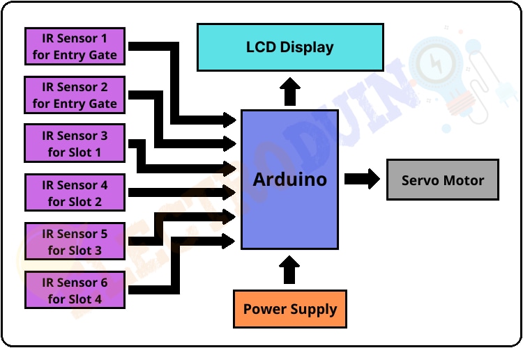
This smart parking system project consists of Arduino, six IR sensors, one servo motor, and one LCD display. Where the Arduino is the main microcontroller that controls the whole system. Two IR sensors are used at the entry and exit gates to detect vehicle entry and exit in the parking area. And other four IR sensors are used to detect the parking slot availability. The servo motor is placed at the entry and exit gate that is used to open and close the gates. Also, an LCD display is placed at the entrance, which is used to show the availability of parking slots in the parking area.
When a vehicle arrives at the gate of the parking area, the display continuously shows the number of empty slots. If there have any empty slots then the system opens the entry gate by the servo motor. After entering the car into the parking area, when it will occupy a slot, then the display shows this slot is full.
If there is no empty parking slot then the system displays all slots are full and does not open the gate.
| Components Name | Quantity |
| Arduino Nano or Arduino Uno | 1 |
| USB Cable for Arduino | 1 |
| IR Sensor | 6 |
| Sg90 Servo Motor | 1 |
| 9V power supply | 1 |
| PCB board or Breadboard | 1 |
| Connecting wires | As required in the circuit diagram |
| Tools Name | Quantity |
| Soldering Iron | 1 |
| Soldering wire | 1 |
| Soldering flux | 1 |
| Soldering stand | 1 |
| Multimeter | 1 |
| Desoldering pump | 1 |
| Wirecutter | 1 |
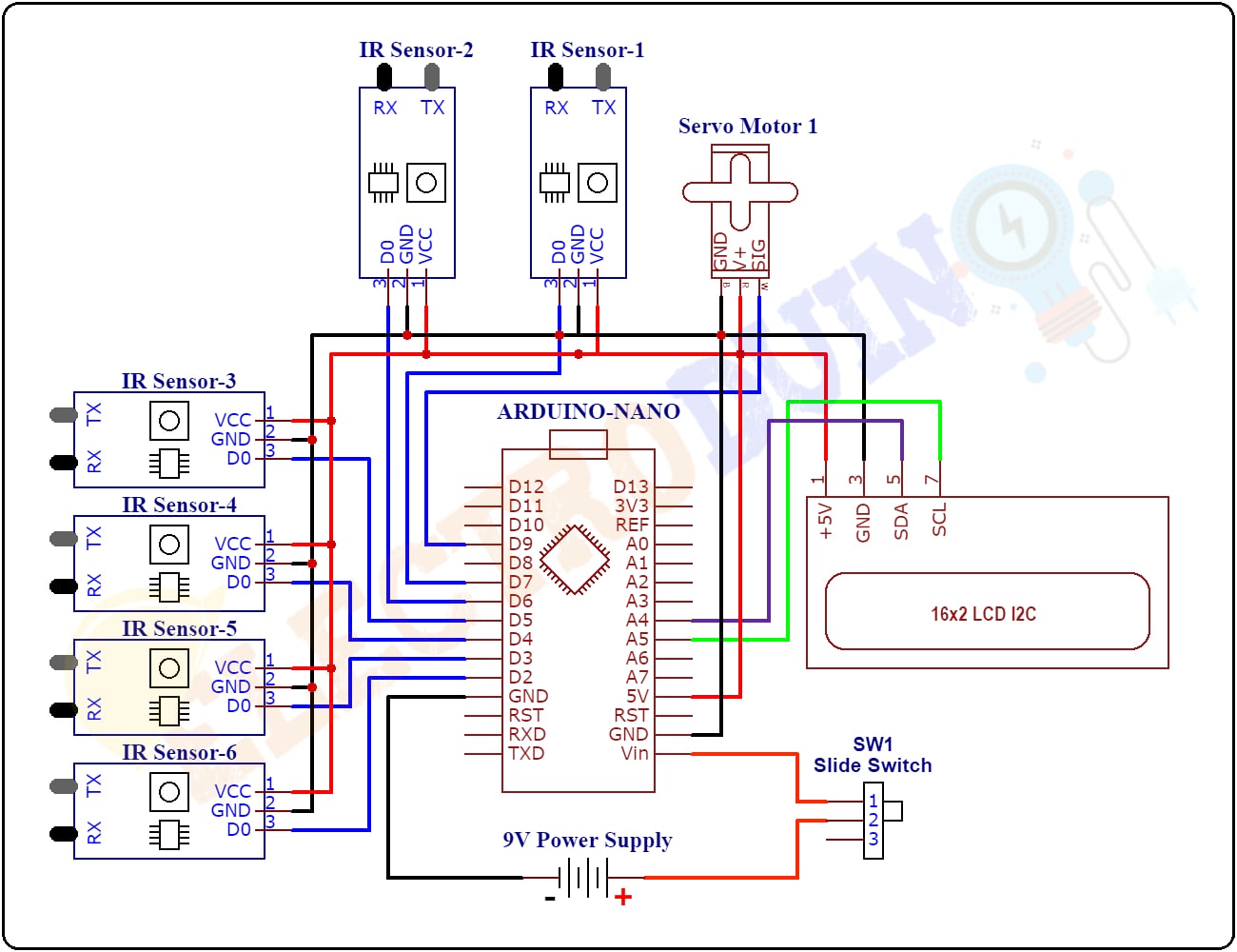
After assembling all components according to the circuit diagram and uploading the code to the Arduino board. Now place the sensors and servo motor at accurate positions.
There are four parking slots in this project, IR sensor-3, 4, 5, and 6 are placed at slot-1, 2, 3, and 4 respectively. IR sensor-1 and 2 are placed at the entry and exit gate respectively and a servo motor is used to operate the common single entry and exit gate. The LCD display is placed near the entry gate.
The system used IR sensor-3, 4, 5, and 6 to detect whether the parking slot is empty or not and IR sensor-1, and 2 for detecting vehicles arriving or not at the gate.
In the beginning, when all parking slots are empty, then the LCD display shows all slots are empty.
When a vehicle arrives at the gate of the parking area then the IR sensor-1 detects the vehicle and the system allowed to enter that vehicle by opening the servo barrier. After entering into the parking area when that vehicle occupies a slot then the LED display shows that the slot is full. In this way, this system automatically allows 4 vehicles.
In case the parking is full, the system blocked the entrance gate by closing the servo barrier. And the LED display shows that slot-1, 2, 3, and 4 all are full.
When a vehicle leaves a slot and arrives at the gate of the parking area then the IR sensor-2 detects that vehicle and the system open the servo barrier. Then the LED display shows that the slot is empty. Again the system will allow entering a new vehicle.
#include //includes the servo library #include #include //includes LiquidCrystal_I2C library LiquidCrystal_I2C lcd(0x27, 20, 4); Servo myservo; #define ir_enter 2 #define ir_back 4 #define ir_car1 5 #define ir_car2 6 #define ir_car3 7 #define ir_car4 8 int S1=0, S2=0, S3=0, S4=0 ; int flag1=0, flag2=0; int slot = 6; void setup() < Serial.begin(9600); // initialize digital pins as input. pinMode(ir_car1, INPUT); pinMode(ir_car2, INPUT); pinMode(ir_car3, INPUT); pinMode(ir_car4, INPUT); pinMode(ir_enter, INPUT); pinMode(ir_back, INPUT); myservo.attach(9); // Servo motor pin connected to D9 myservo.write(90); // sets the servo at 0 degree position // Print text on display lcd.begin(20, 4); lcd.setCursor (0,1); lcd.print(" Smart Car "); lcd.setCursor (0,2); lcd.print(" Parking System "); delay (2000); lcd.clear(); Read_Sensor(); int total = S1+S2+S3+S4; slot = slot-total; >void loop() < Read_Sensor(); lcd.setCursor (0,0); lcd.print(" Have Slot: "); lcd.print(slot); lcd.print(" "); lcd.setCursor (0,1); if(S1==1) < lcd.print("S1:Fill "); >else < lcd.print("S1:Empty"); >lcd.setCursor (10,1); if(S2==1) < lcd.print("S2:Fill "); >else < lcd.print("S2:Empty"); >lcd.setCursor (0,2); if(S3==1) < lcd.print("S3:Fill "); >else < lcd.print("S3:Empty"); >lcd.setCursor (10,2); if(S4==1) < lcd.print("S4:Fill "); >else < lcd.print("S4:Empty"); >/* Servo Motor Control ***********************/ if(digitalRead (ir_enter) == 0 && flag1==0) // read degital data from IR sensor1 < if(slot>0) < flag1=1; if(flag2==0) < myservo.write(180); slot = slot-1; >> else < lcd.setCursor (0,0); lcd.print(" Sorry Parking Full "); delay(1500); >> if(digitalRead (ir_back) == 0 && flag2==0) // read degital data from IR sensor2 < flag2=1; if(flag1==0) < myservo.write(180); // sets the servo at 180 degree position slot = slot+1; >> if(flag1==1 && flag2==1) < delay (1000); myservo.write(90); // sets the servo at 90 degree position flag1=0, flag2=0; >delay(1); > void Read_Sensor() < S1=0, S2=0, S3=0, S4=0; if(digitalRead(ir_car1) == 0)// read degital data from IR sensor3 if(digitalRead(ir_car2) == 0) // read degital data from IR sensor4 if(digitalRead(ir_car3) == 0) // read degital data from IR sensor5 if(digitalRead(ir_car4) == 0) // read degital data from IR sensor6 >